Doug Hylan conveniently provided a single sheet for the construction of the strong back and positioning of the molds. Then he provided a separate sheet with full scale layouts of the mold profiles.

I reused an old strong back from my Seaford Skiff build and extended it to the full 17′ 6″. Doug called for 2 x 8 supports. The old one was made from 2 x 6s. I just went ahead with that and reinforced them along the length.
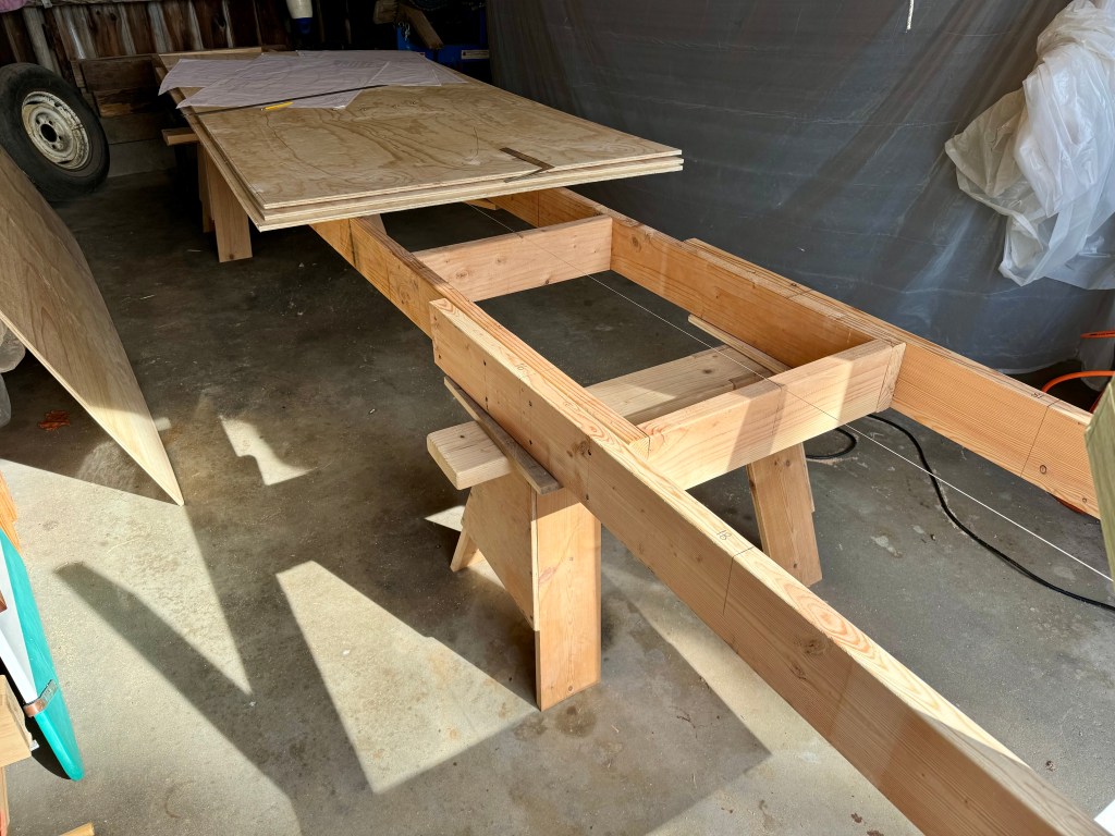
Angled supports were attached to the strong back. They temporarily supported the transom. Of course, Doug provided a drawing of the appropriate angle and position!


Then it was a simple matter to layout the molds according to the full scale profiles on the drawings. I used 1/2″ plywood with a support brace at the bottom. The drawings called for 3/4″ plywood molds. But, as cost was an issue, I used the 1/2″ and reinforced the centers to assure flatness. I used scrap to brace each mold. It is plenty stiff.

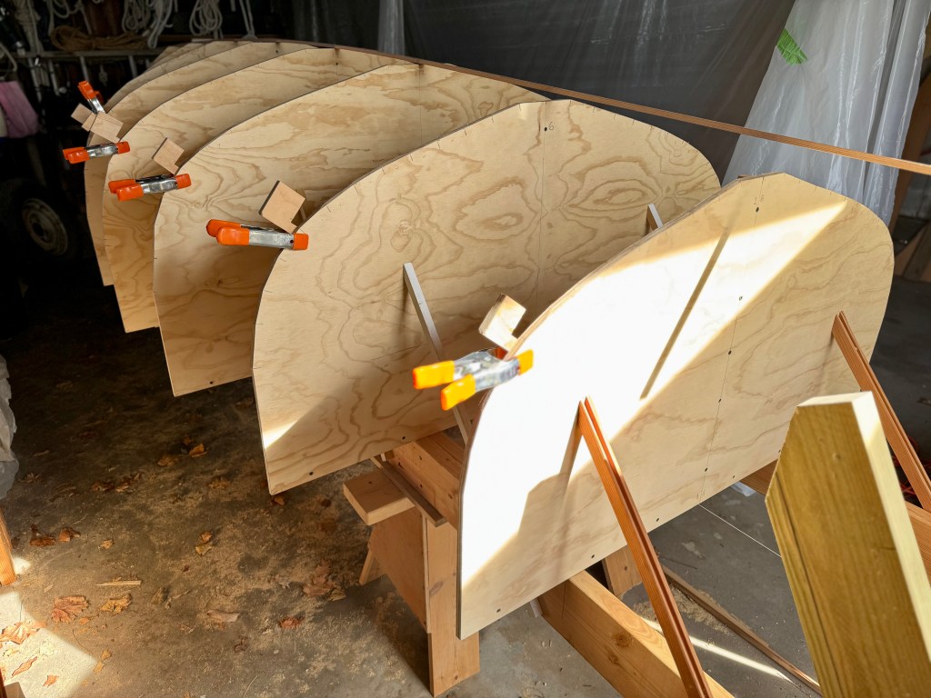
The next step was fairing the edges of molds. A batten was used to find the correct bevel for each plank edge support. The drawings called for the molds to be positioned on the center line of the mold edge. I am not used to this. Usually they are positioned to one side or another for and aft changing at the mid point. With positioning at the center line only half the edge is beveled – a tedious process. Not sure why this was done this way.

Now onto the keel, stem and transom.

Leave a comment