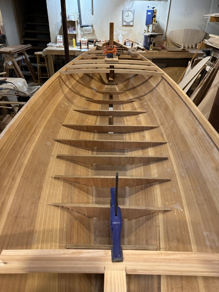
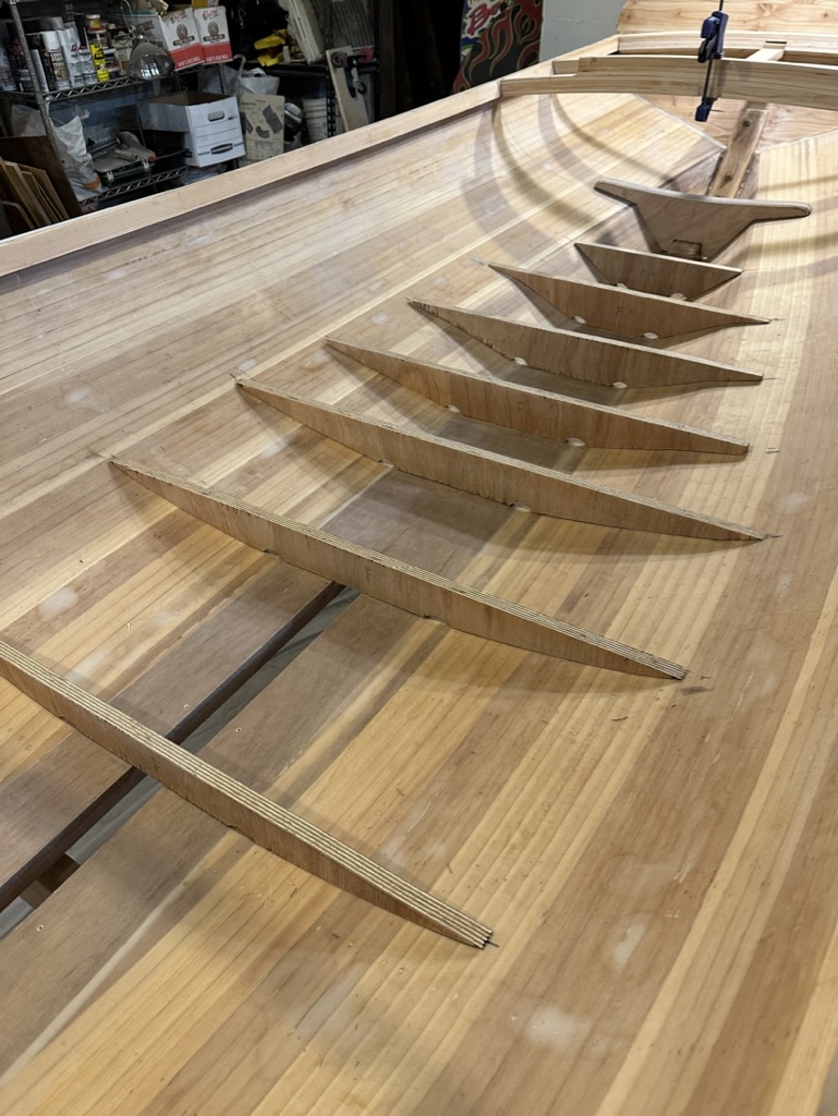
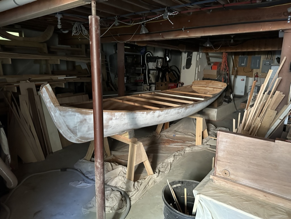
Using 3/4″ marine plywood I made the floors to support the floorboards. They would also add stiffness to the hull. Coated in epoxy they were then glued into the hull with large fillets. The few at the centerboard opening were cut later and glued after the trunk was installed. I made some floorboard templates with 1/4″ ply to get the right shapes to fit the curves of the hull and establish the height of the floors. The 1870s originals had no floorboards. Must have been a bit wet sitting in the bilge water! Also that tunnel keel at the stern looks a bit uncomfortable! I prefer floorboards.

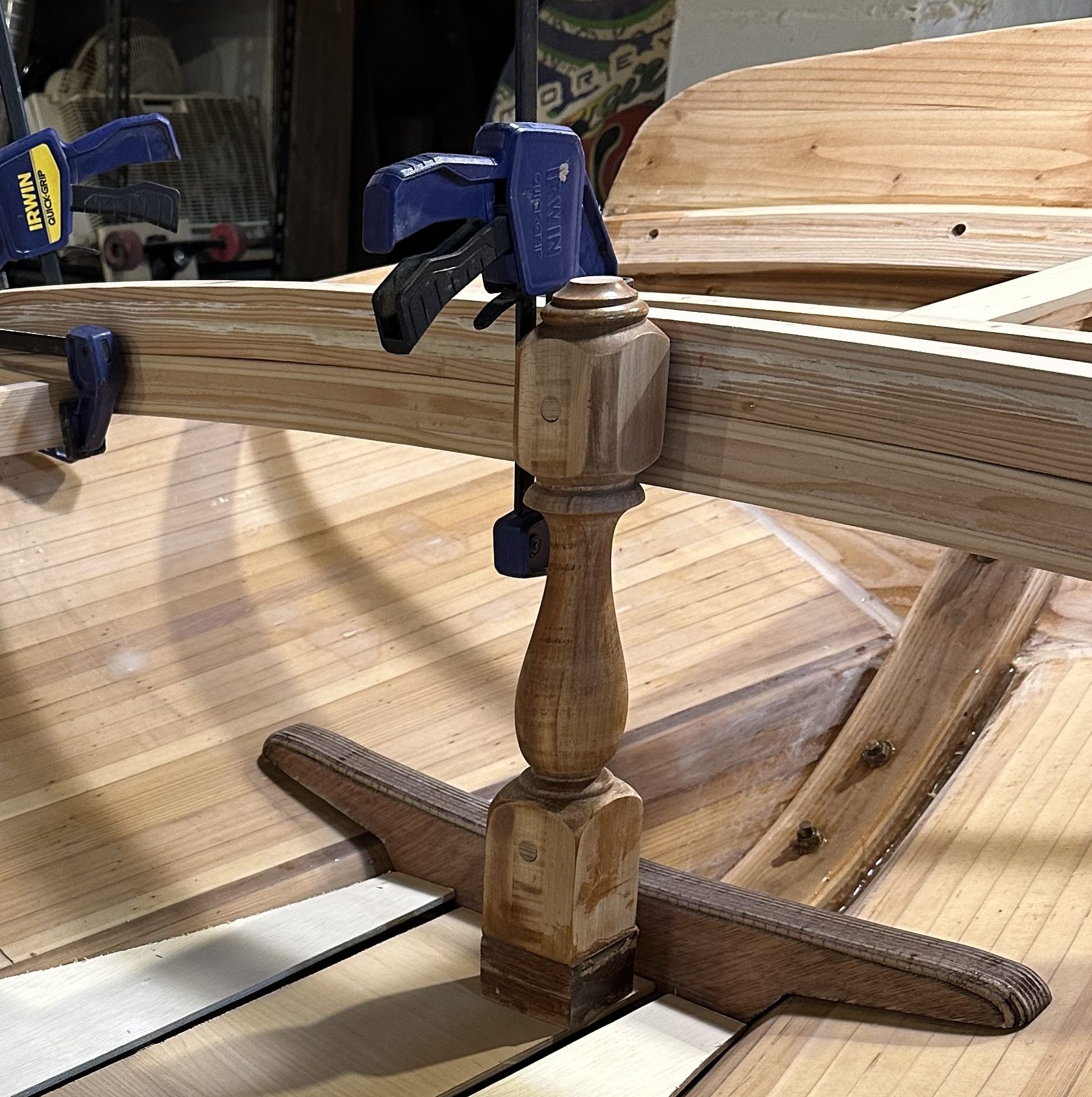
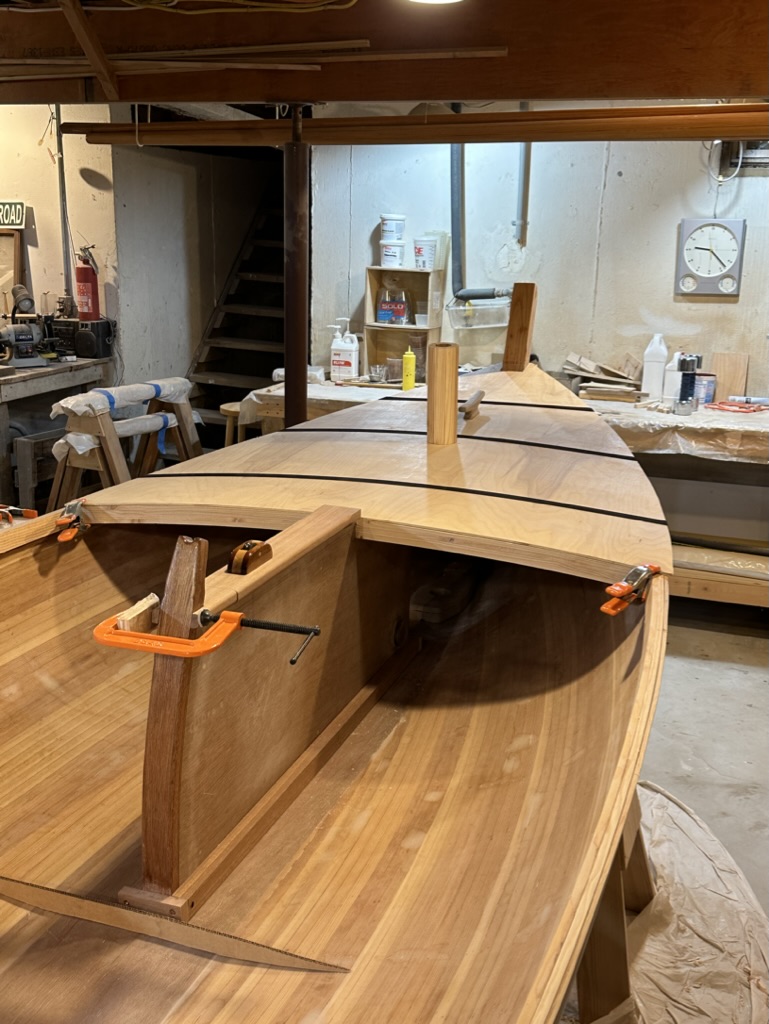
Staying with tradition, I used a maple finial from an old bed headboard to support the aft deck beam. It is visually a bit heavy, but worked fine.
I put in a few knees to support the side decks. While probably not necessary, as the cockpit deck framing would be reinforced with the deep mahogany coaming, I thought some additional strength there would be a good idea if I rolled the boat on its side to turn it over. I was still concerned about the 1/4″ cedar hull thickness.

Because I was making the boat in my basement I needed to get her up and out through the scuttle. I did some crazy calculations before I chose the Seaford Skiff design to assure myself it would fit through the narrow opening. It would need to be tilted diagonally with only a couple of inches on each side to clear the opening.
While making the deck structure I became concerned about the weight of the boat. Hauling it up the steps of the scuttle would be hard enough given the awkward orientation. As a result I made the entire deck structure removable to lighten the boat. I would glue and screw it permanently once I moved her into the garage in the spring.
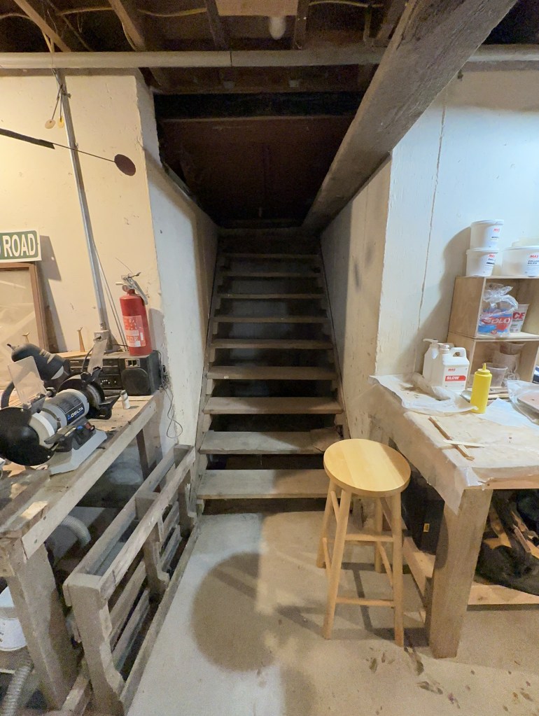
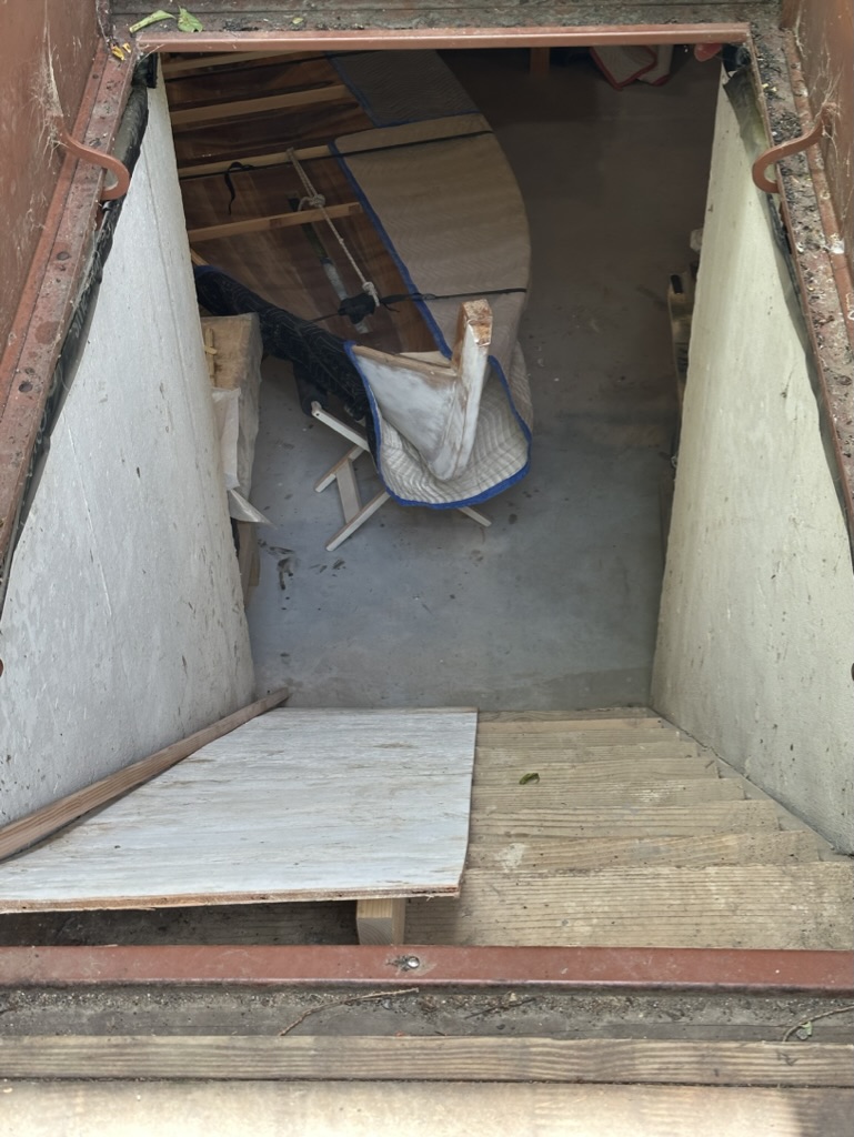
The “Infamous” Scuttle
I used laminated Doug fir 3/4″ x 1 1/2″ for the cambered deck beams. I made a few masters to use as guide templates for fairing. Starting at the forward end, I notched and reinforced the beams to engage the centerboard trunk, which sits well out into the cockpit without horizontal support. I then proceeded with the stern beams and side deck beams. I made the mast partner and notched it into the beams forward. The breasthook came next, and I added some partners at the shear clamps to resist the horizontal forces of the unstayed mast. All the beams were morticed into the shear clamp. I faired the entire deck structure, checking often with a batten fore and aft for a nice sweeping curve. Most of that was done by eye. With all the loose parts just resting in the mortices, this was not easy – small clamps came in handy.


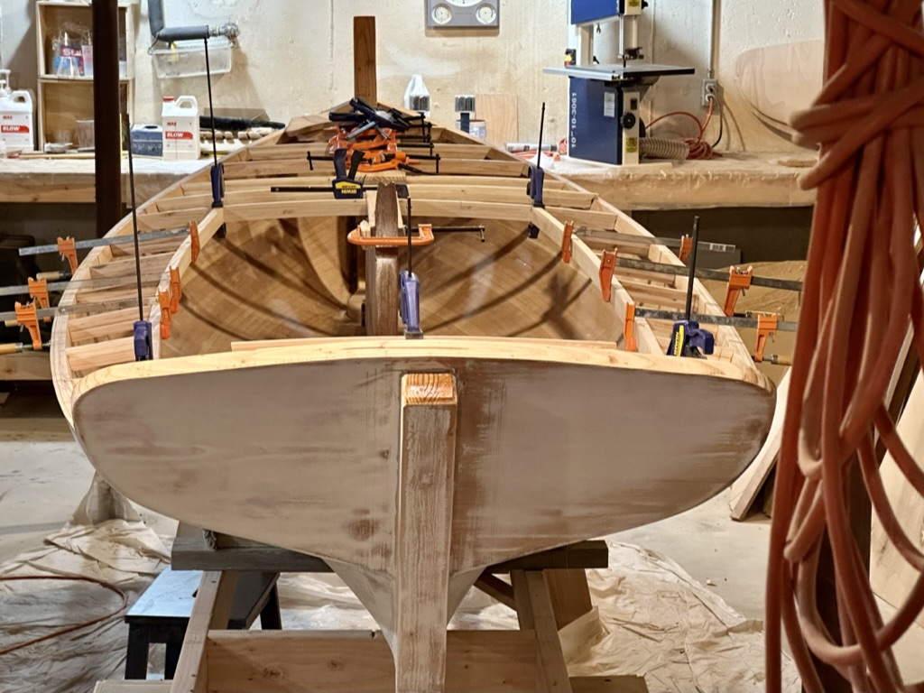
I made a template of the fore and aft decks with 1/4″ ply to make sure the camber looked smooth. One appealing feature of this design was the curve of the shear in concert with the sweep of the deck fore and aft. The camber of the decks at 2″ to 22″ was all part of that visual concert.

Then I removed everything, carefully marked all the pieces, and put in some temporary horizontal shear supports for the trip out the scuttle. I padded her with packing blankets where she would undoubtedly rub against the wall of the scuttle. She was ready to travel. I just hoped that my calculations were correct because cutting the boat in half was not a viable alternative. Onward!

Leave a comment