
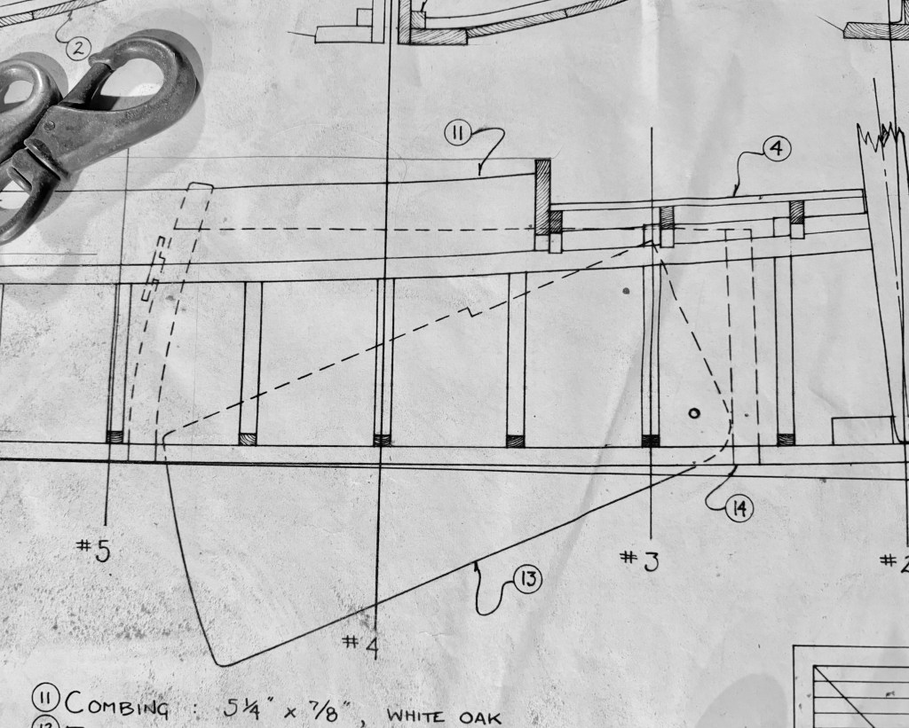
Plans Profile of Centerboard and Trunk
The lack of detail in the plans began to raise its head at this point. There were precious few dimensions given for the size and shape of the centerboard and only two or three for the trunk. In fact, the plan profile and the cross section showed two different outlines for the centerboard. At least the pivot point was well-documented. The trunk was fairly easy to figure out as there were a few base dimensions and the rest was a matter of establishing height – which I could estimate from station lines and a bit of scaling from the drawings.
It was the centerboard that was my concern. So, off I went to calculate the CE and CLR. There were other voodoo calculations involved but, most importantly, I wanted the proper balance of effort to resistance. As the 1870s originals carried a smaller winter sail and larger summer sail, the calculations were an average. I also had to establish the amount of overlap of the centerboard with the exit point of the trunk for maximum support when the board was down. Both the board and the trunk would be glassed so there would be considerable strength in the assembly.
Plans Cross Section of Centerboard and Trunk
First I made the board out of 3/4″ marine plywood and then sized the trunk with clearances anticipating thicknesses of glass, epoxy, and bottom paint. Nothing is more bothersome than a banging centerboard in its trunk, so the clearances were nice and tight – not TOO tight! Then I made the trunk based on the centerboard dimensions. I mildly tapered the leading edge of the board to a shallow foil shape but did not overdo it as it would be vulnerable if the boat grounded. I also cut the hole for a pour of a few pounds of lead so the board would not float up.
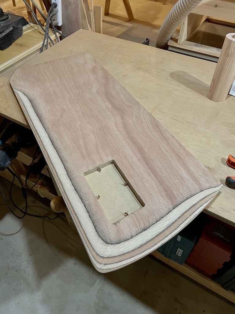
Centerboard
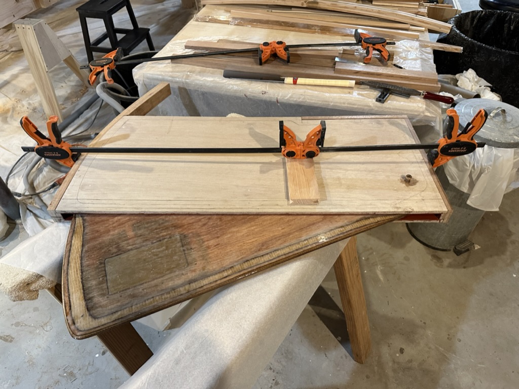
Centerboard and Trunk Assembly
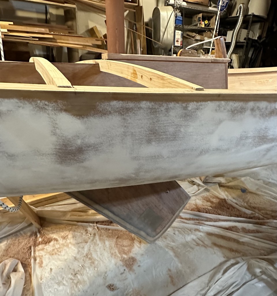
As I was building the trunk I made sure it fit tightly over the contoured keel. Using a lot of string and plumb bobs I found the critical centerline of the hull and located the trunk in preparation for cutting a hole for the board. The sides of the trunk would project down through the hole for added structural support. This part of the trunk was effectively a vertical cantilever so the additional bearing area glued to the 1 1/4″ keel depth, together with the base cleats, would give maximum stiffness.
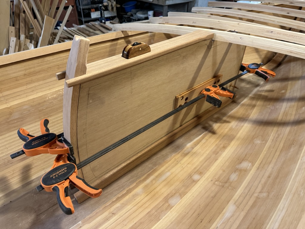
Temporary Trunk Positioning
I used a bronze bushing to line the pivot hole in the trunk. The pin is a bronze bolt with the threads filed down (what I had). Another bronze bushing lined the hole in the board for the pivot pin. To secure the board in the up position to relieve standing strain on the centerboard pennant I made a holding pin. It was made out of a stainless fast pin and brass plate.
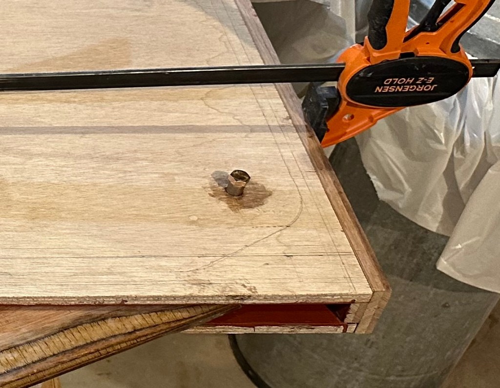
Bronze Bushing
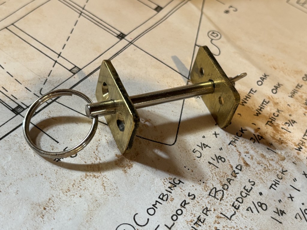
Holding Pin for the Up Position of Centerboard
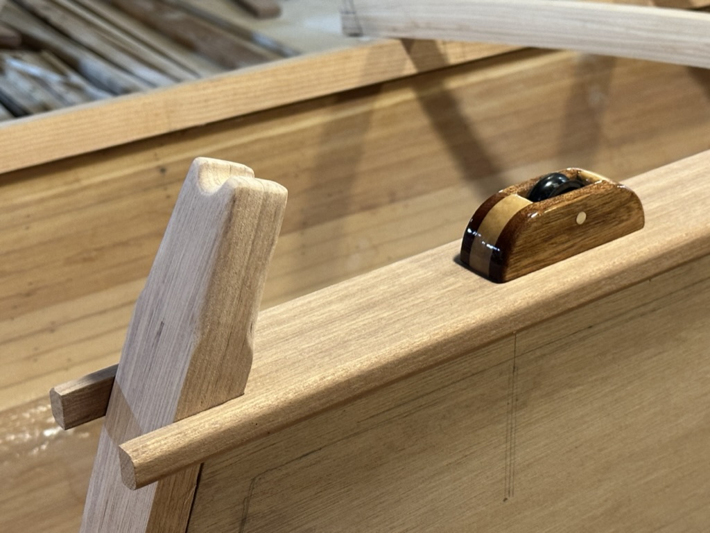
I made a removable cover board for the trunk. If I needed to push the board down should it get fouled or jammed, I could do this while in the boat. I placed a turning block on top of the cover board at the pennant exit point. I made the block out of white oak, mahogany, and a bronze pin. I used a delrin sheave that I had lying around.
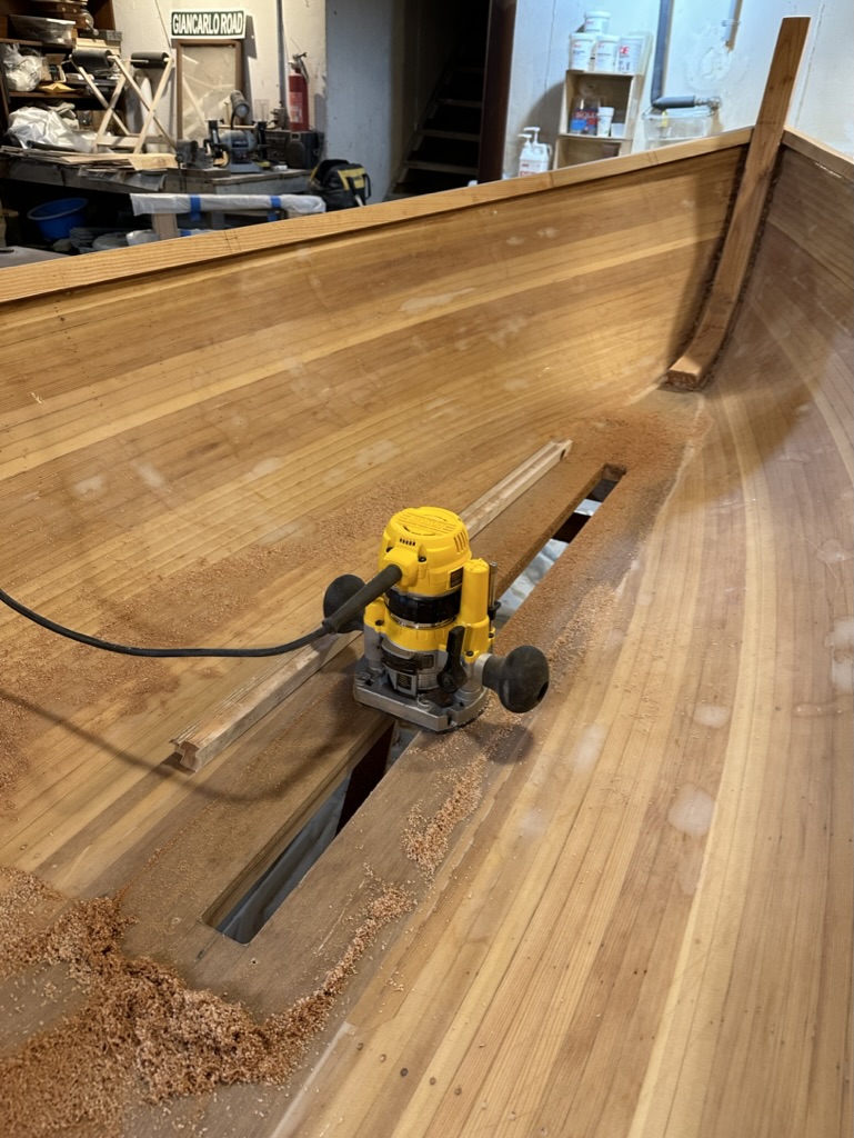
I then made a template and guide for the centerboard opening. I used a router to cut the hole. As terrifying as it is to cut holes in the bottom of boats, once cut, there is a certain satisfaction and relief when everything fits perfectly. Before that, you need to steel yourself to start the cut!
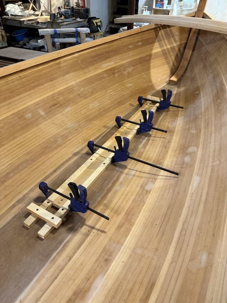


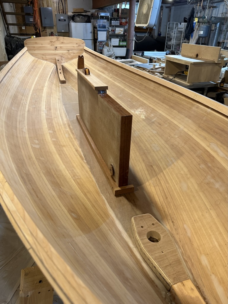
Testing out the Centerboard Fit
The centerboard fit nicely – no slop to drive me crazy banging around in the trunk and it moved smoothly up and down. The pennant pull angle was good and later I would just tie a knot in the pennant to set the maximum depth of the board.
At this point I installed the mast step. Having laminated several layers of 3/4″ marine plywood I screwed and glued it to the keel and stem. Thankfully, its position was given in the plans. The rake of the mast would come later when I made the partners.

Leave a comment