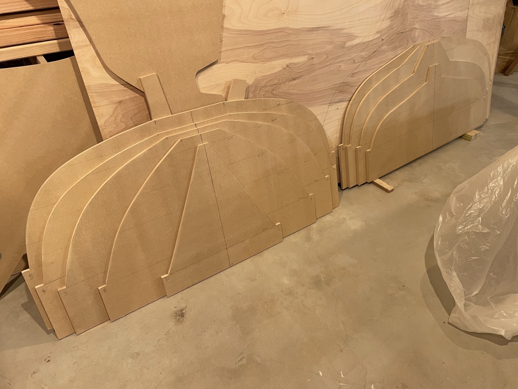
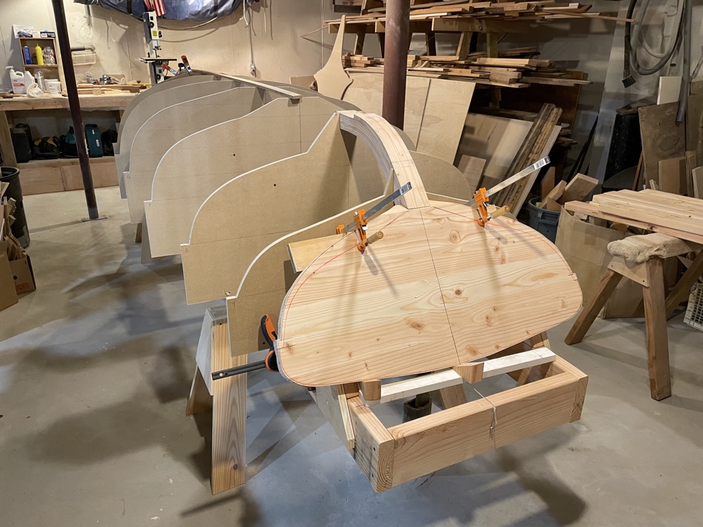
Once corrected, the offsets were easily transferred to 3/4″ MDF to make the molds. Because the cedar planking strips would be set on the high edge of the station lines fore and aft, I didn’t bevel the edges. The cedar would span the small variations. I rough cut the molds with a saber saw then planed and sanded down to the final dimensions. I left a small ledge to establish the shear and then added some extra dimension to the bottom strongback edge to make sure they extended enough so that the hull would clear the stem and stern. I labeled them carefully for centerlines, station numbers, and waterline offset marks. Using a pen is a good idea as pencil tends to rub off as work progresses.
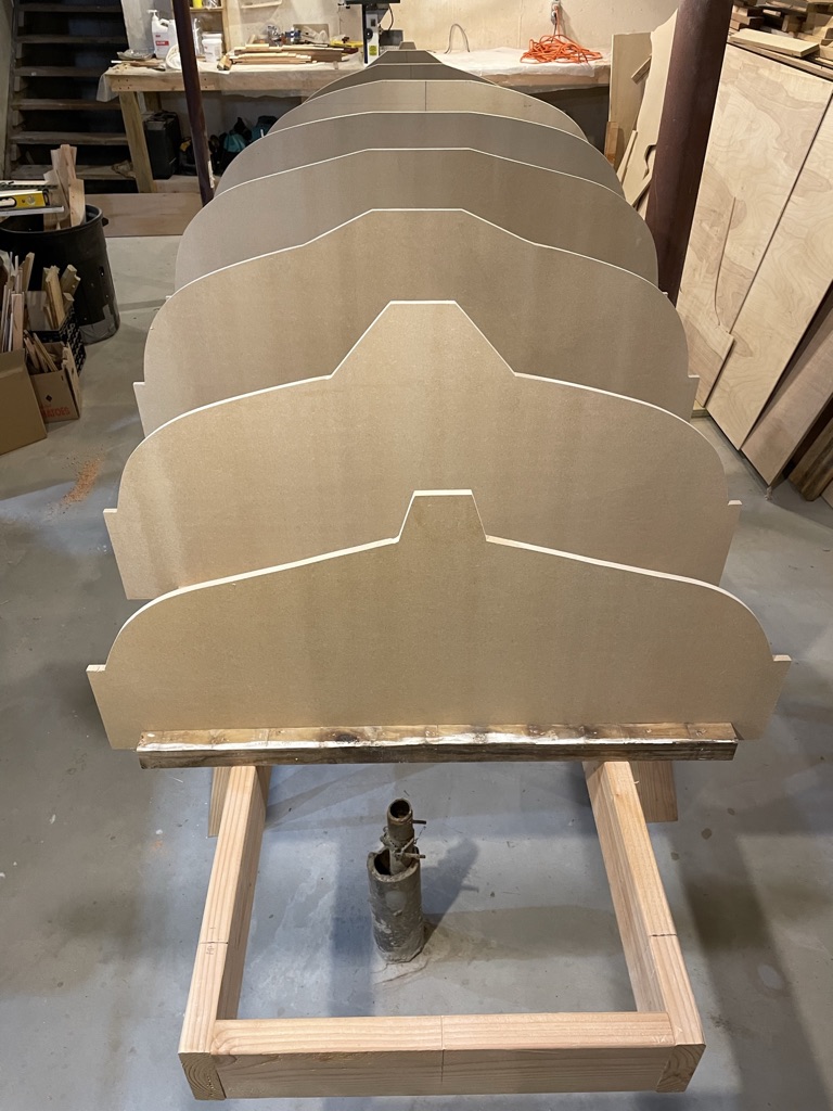
The strong back consists of 2x6s on low saw horses. Always a good idea to make sure the sawhorses are the right height so the keel is easily reachable without a stool. I guessed at the length, assuming if I made it a bit long, I could figure out the supports for the stem and transom later. Cross members were put on the station lines and coordinated with the proper edges of each mold. Everything was leveled and squared. I was working on a concrete floor which luckily was quite level, so few shims were needed.

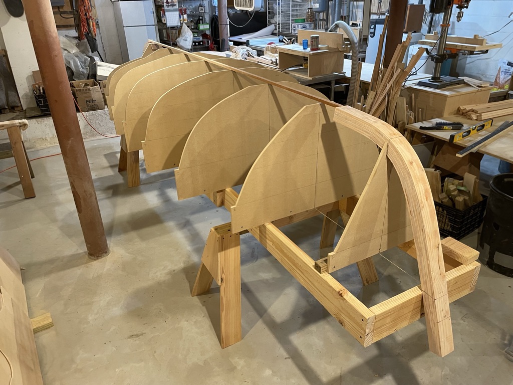
Next I added cleats to the bottom of the molds, positioned and aligned with the station lines on the strongback. Accuracy here was paramount. Vertical leveling was achieved with diagonal supports. The fore and aft molds would wait to be leveled until I could use the laminated stem and stern to position them accurately. In the photo below you can see the unusual “tunnel skeg” mold at the aft end.
Testing the molds on the Strongback

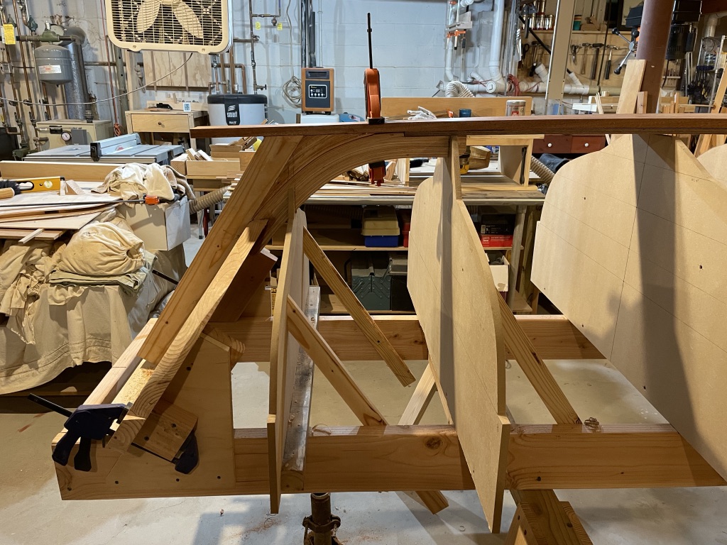
Using the laminated stem and stern I positioned the fore and aft molds. I cut the notches in the molds and fit the laminations tightly and leveled and aligned them carefully. A stiff batten made sure the molds were well aligned at the keel line fore and aft. It would be quite a bummer to have things twisted and find out she wanted to sail askew!

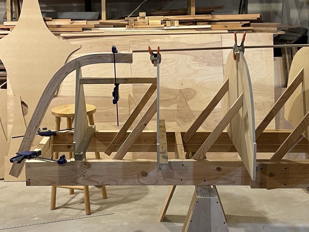
Setting the transom took some time. Getting the proper rake, centering and leveling, making sure the stern laminations were aligned and tight, inventing a temporary support structure that would hold things firmly, all took a full day. Trim here, recut there, make a “thing-to-make-a-thing,” a few templates to make sure, and it was positioned. The test was when I positioned the stern post and it fit correctly – no gaps.

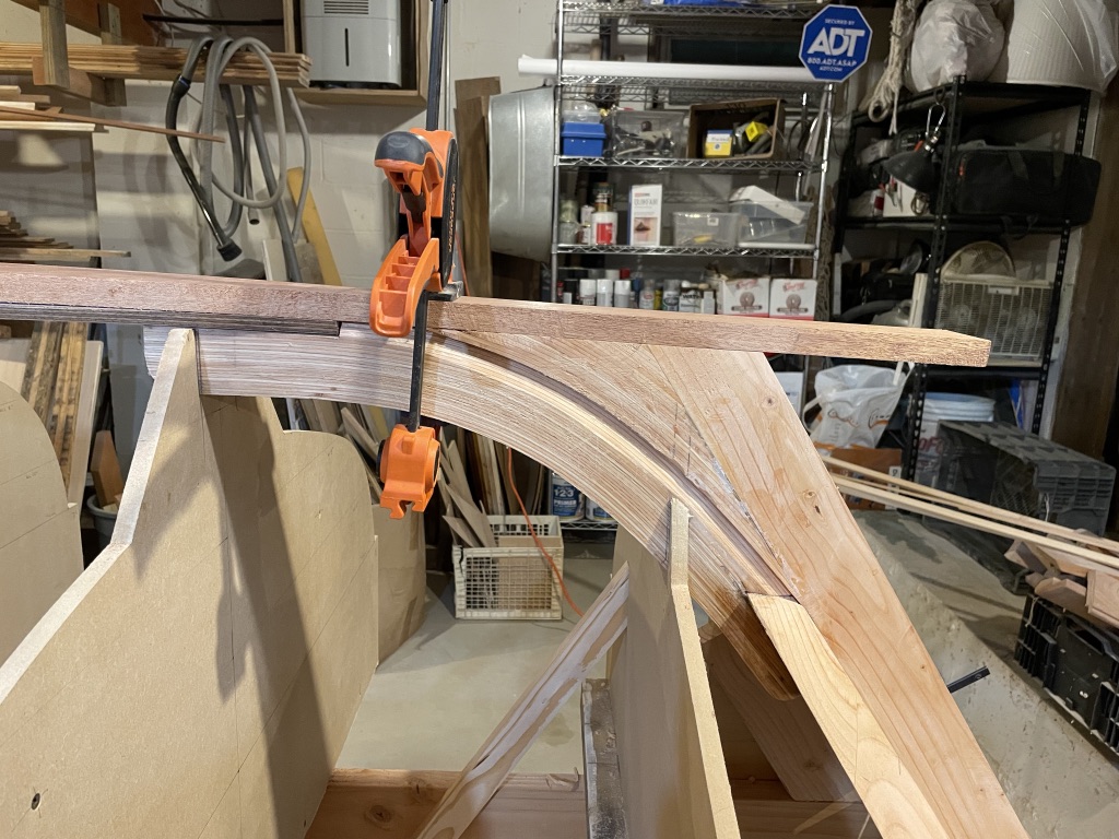
To achieve the appropriate rolling bevels on the stem, stern, and transom I used a length of the same cedar strips I would be using to build the hull. To cut the proper bevel I clamped the cedar strip to several molds adjacent and cut the bevel every few inches. Then I smoothed the whole bevel carefully. The epoxy laminated fir cut surprisingly easily with a rasp and a chisel.
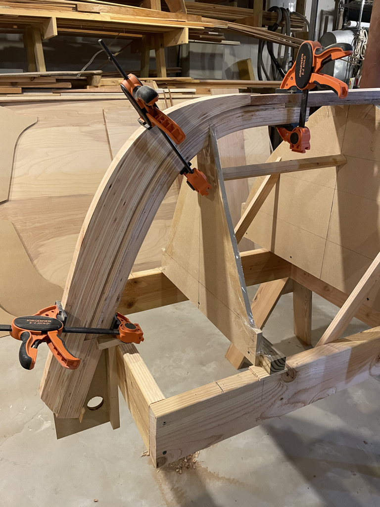
At this point I made a 1/2″ Marine plywood subkeel to accept the cedar strip planking. I made rolling bevels along each side for the 1/4″ cedar planking. Then I made the 5/8″ mahogany keel plank which would go on top of the subkeel and stand proud. This gave me an overall thickness of 1 1/8″. I wanted to avoid splicing and found a nice mahogany plank 16′ long – which cost a pretty penny! On the Seaford Skiff the keel plank is quite wide at 12″.
Then it was a matter of gluing it all together with epoxy. I waited a few days for it to set well. I also carefully trimmed and fit the false stem, stern post, and false skeg.

Leave a comment